Home page » Pins/Devices for fixing thermal insulation

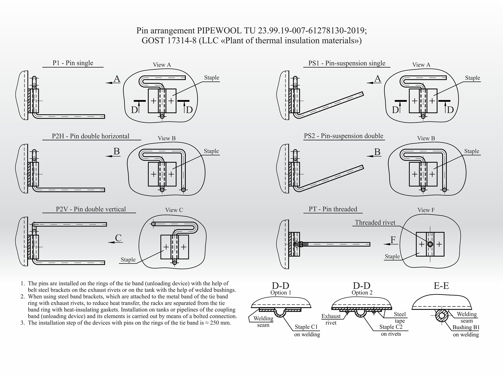
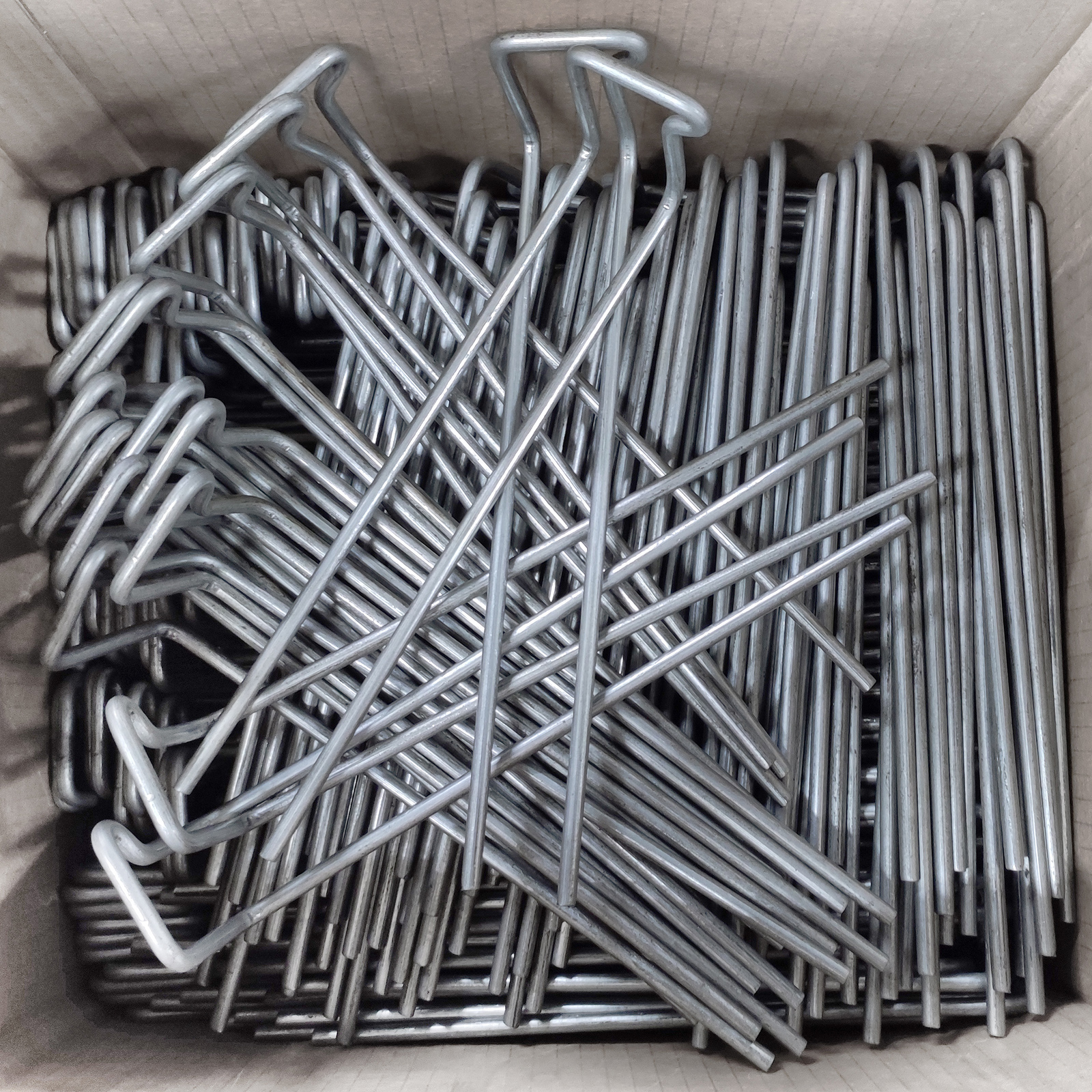
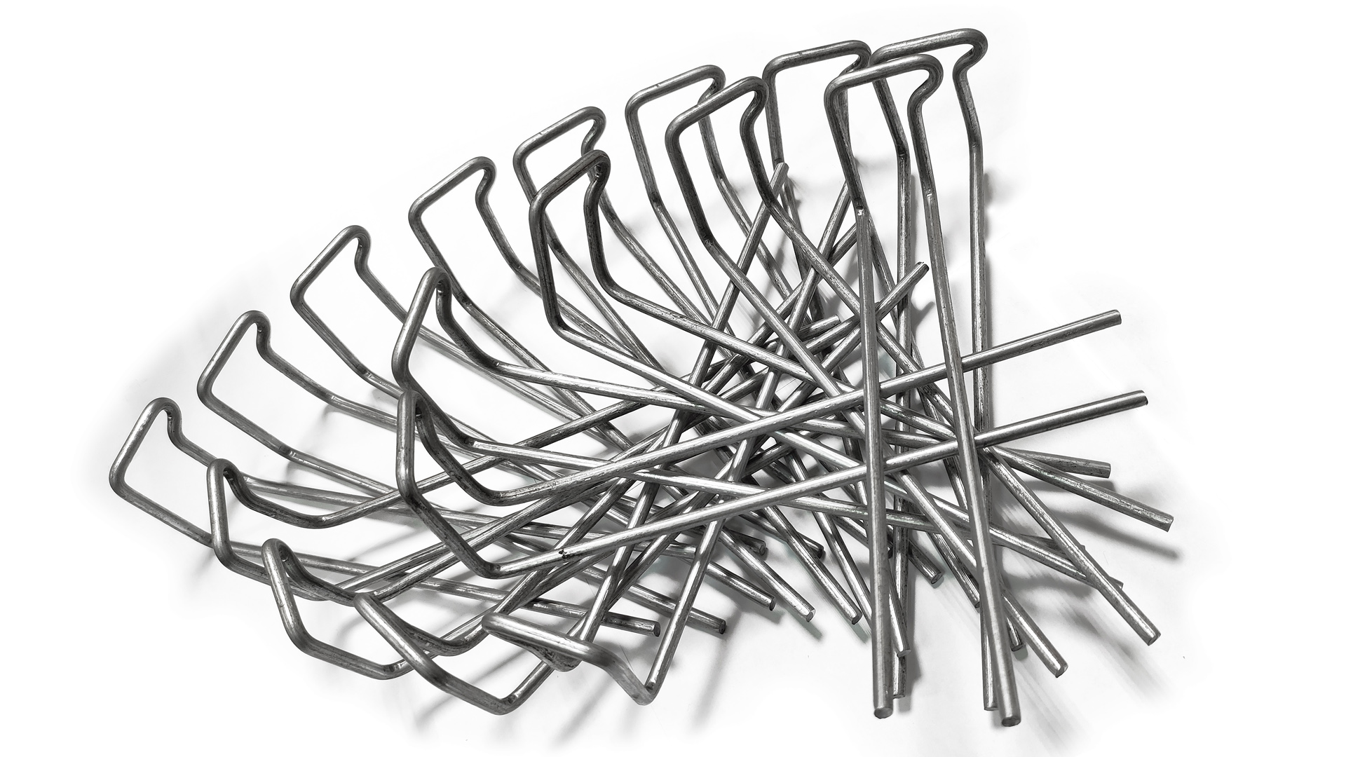
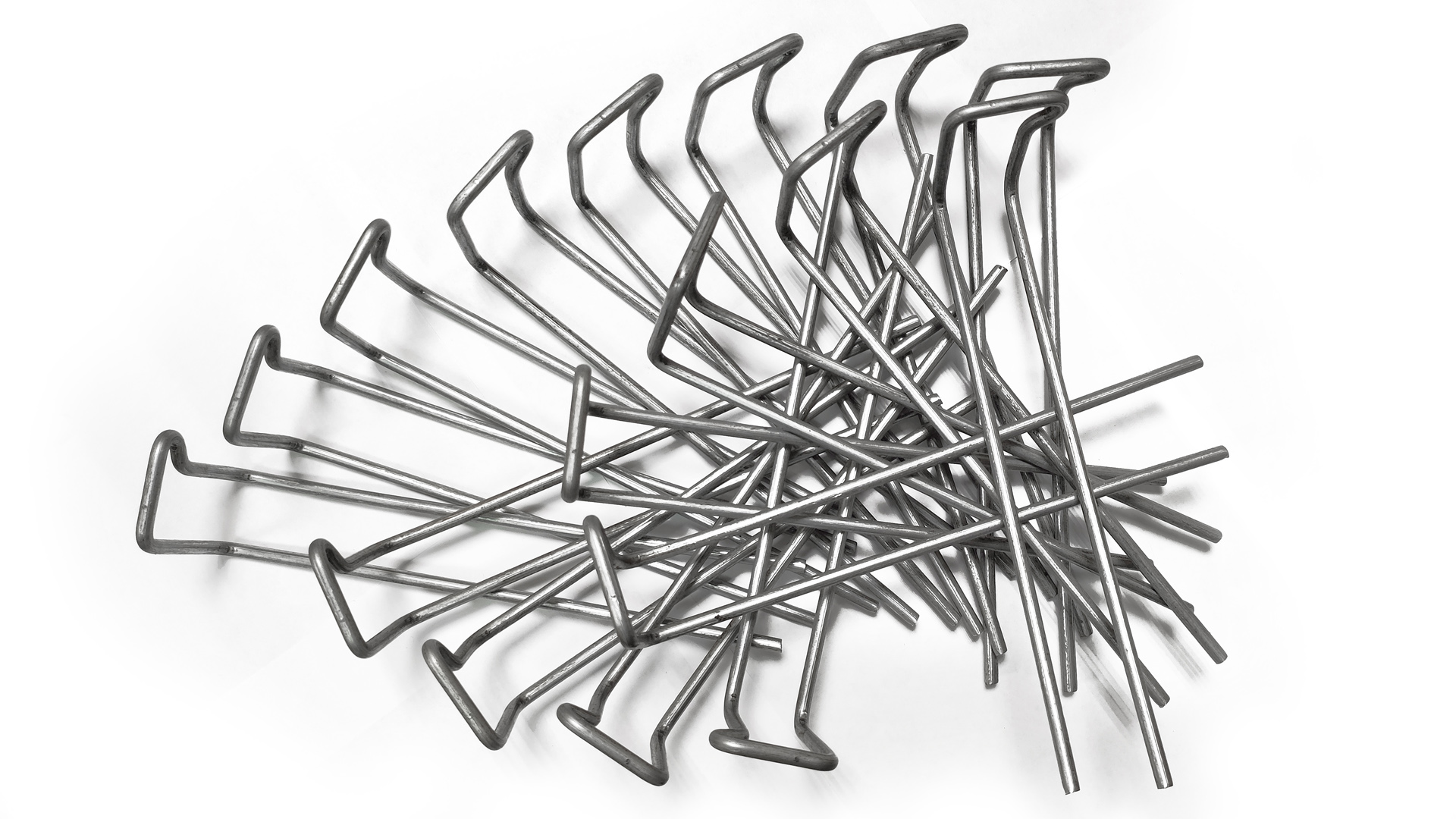
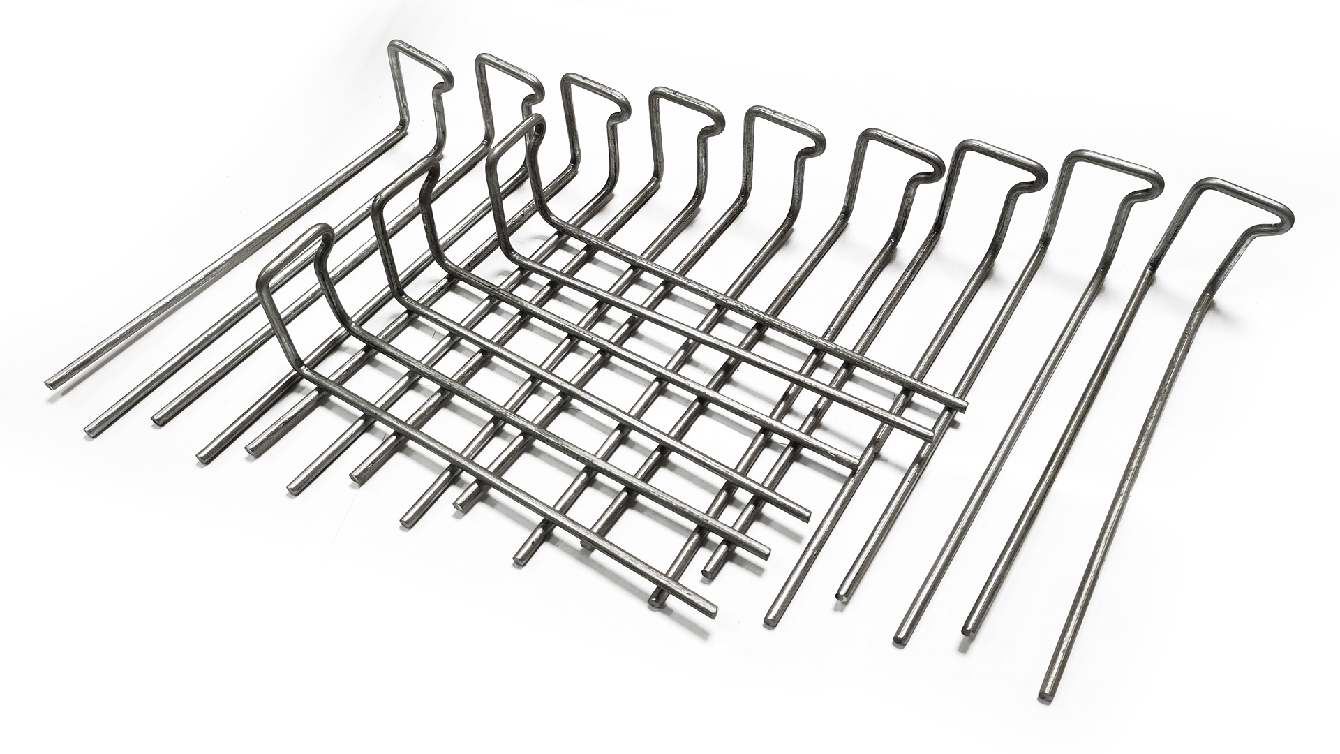
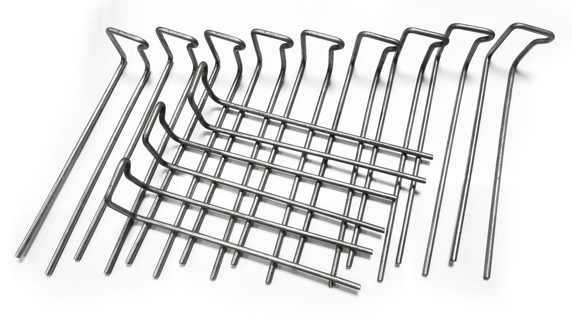
For fixing the main thermal insulation layer on devices and tanks, we have developed and improved existing structures made of single P1 and double P2 pins (GOST 17314-81), the production of which is carried out on automatic CNC lines made of wire steel with a diameter of 5 mm.
Fastening with pins is less labor-intensive and less expensive than with clamps and is used to isolate devices with a diameter of 500 mm, of various heights and lengths.
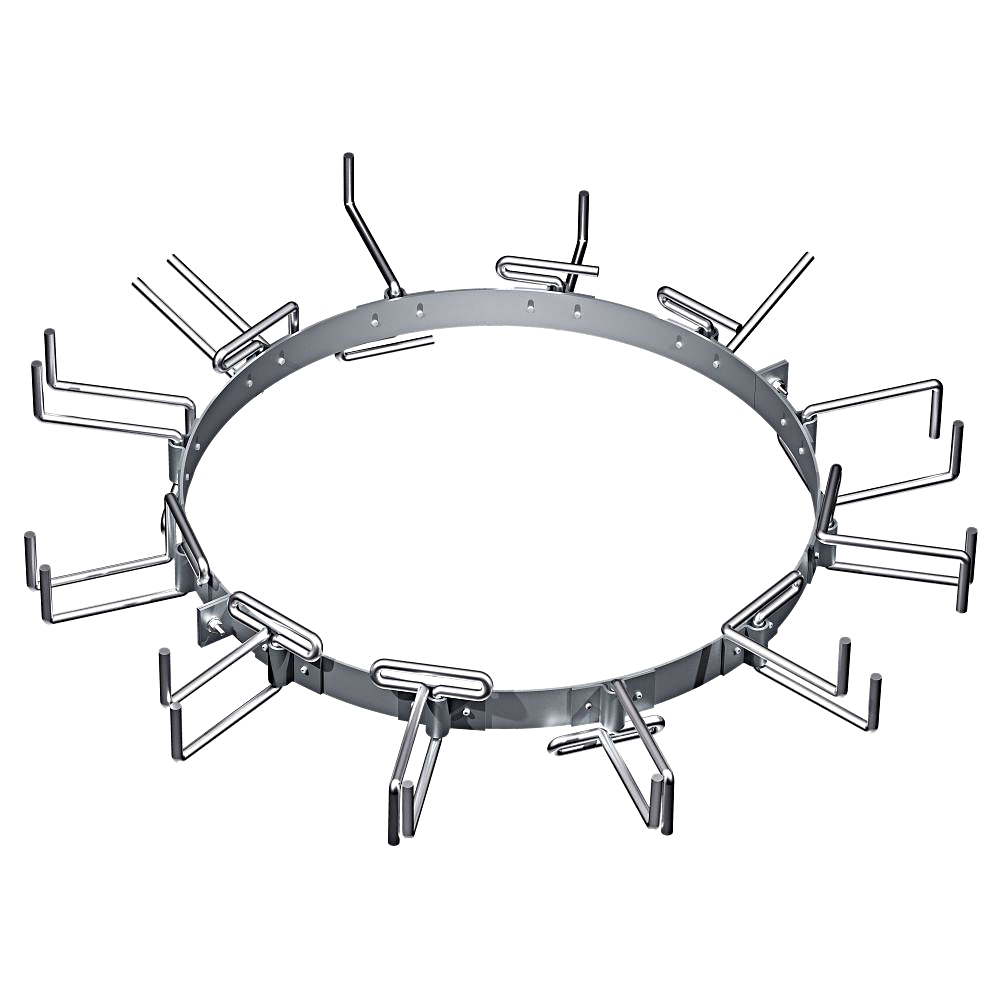
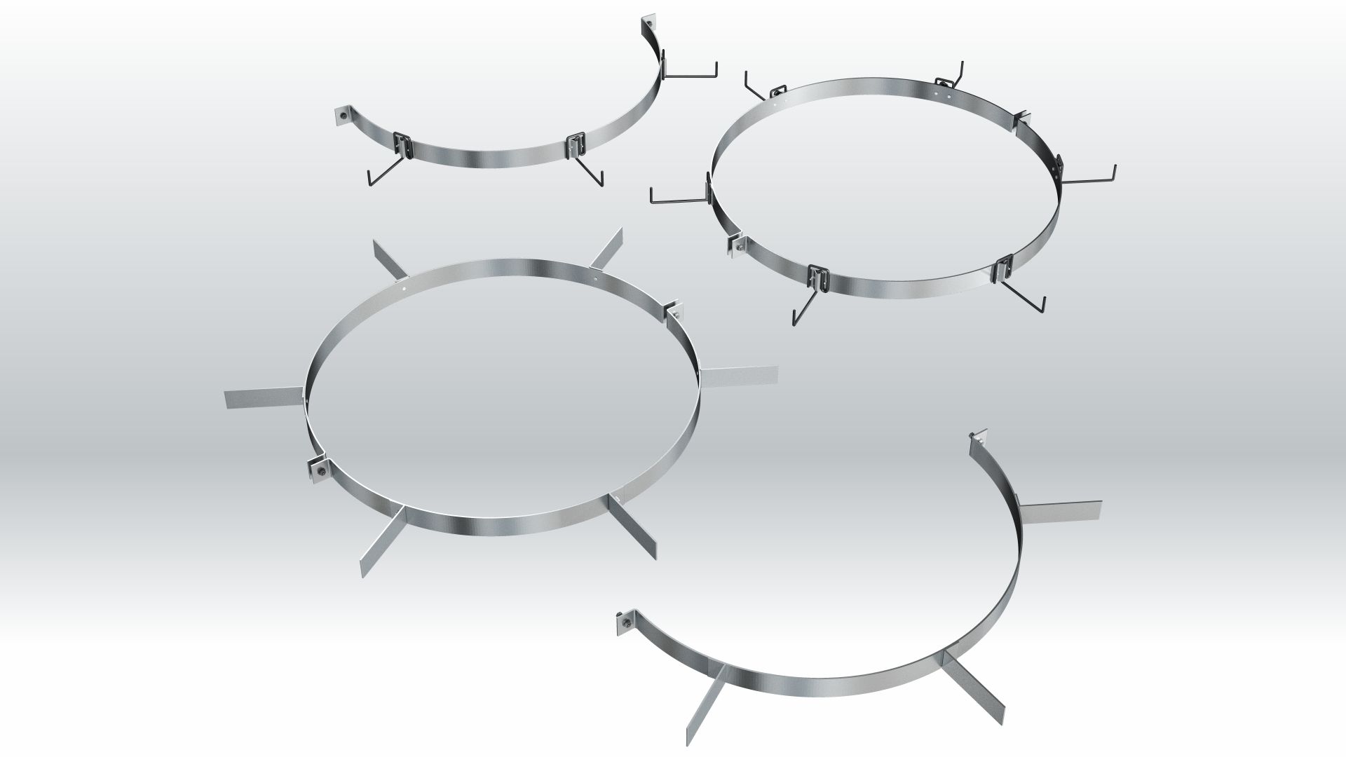
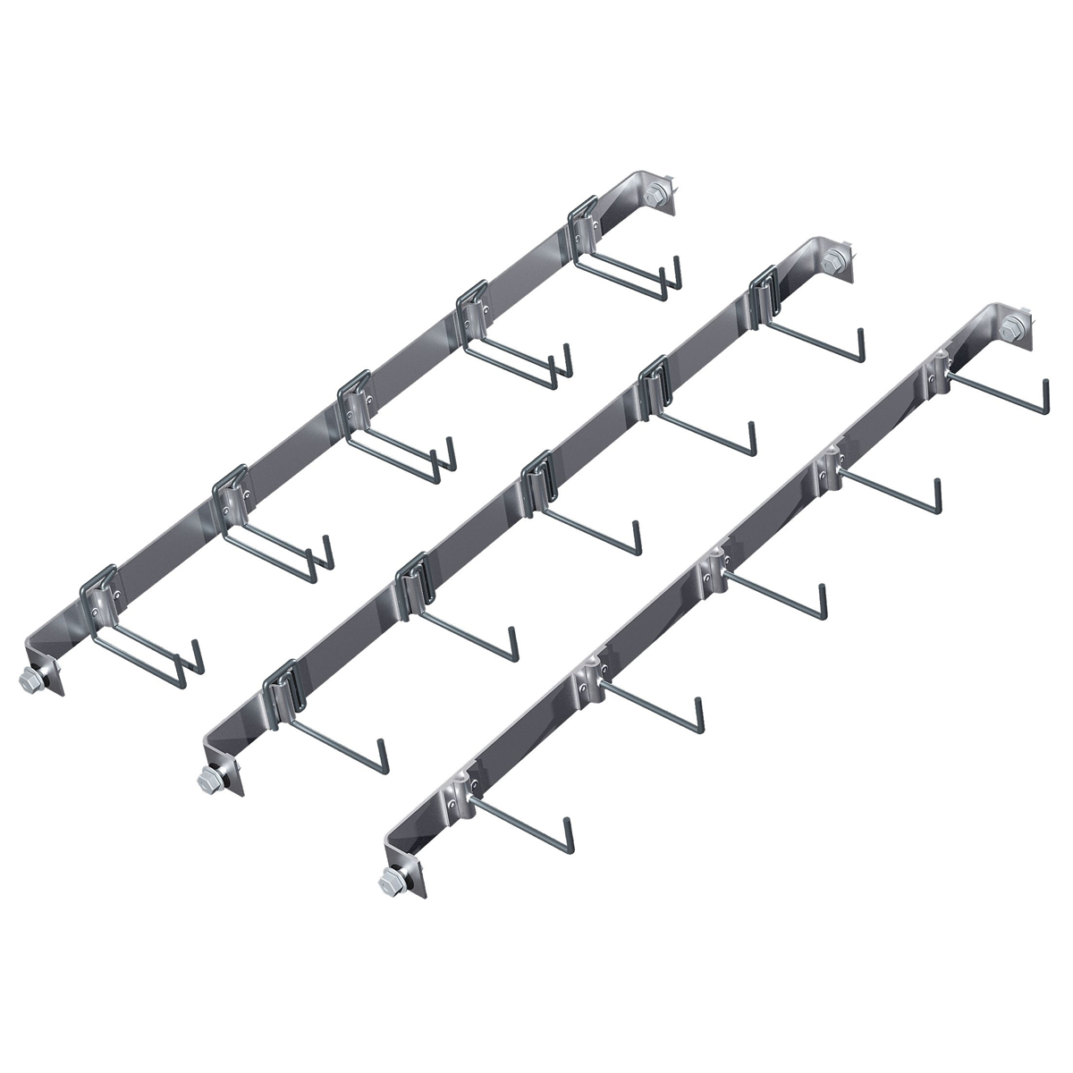
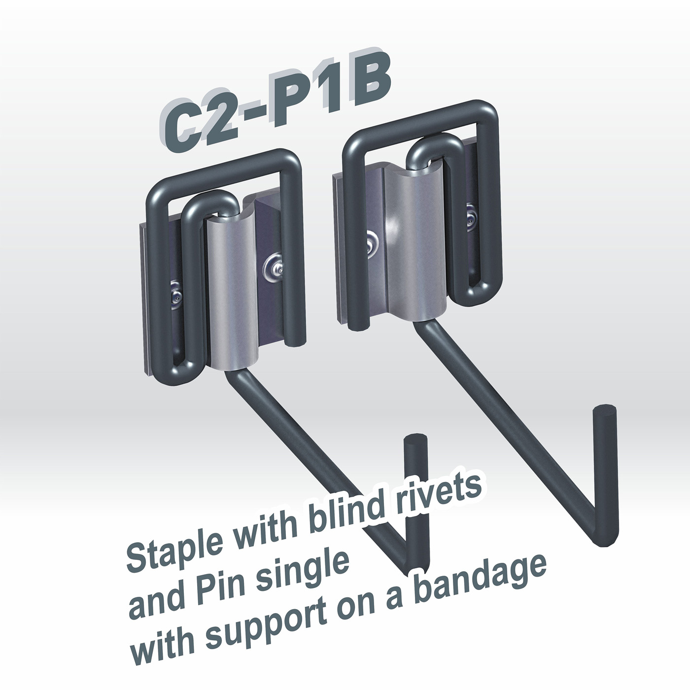
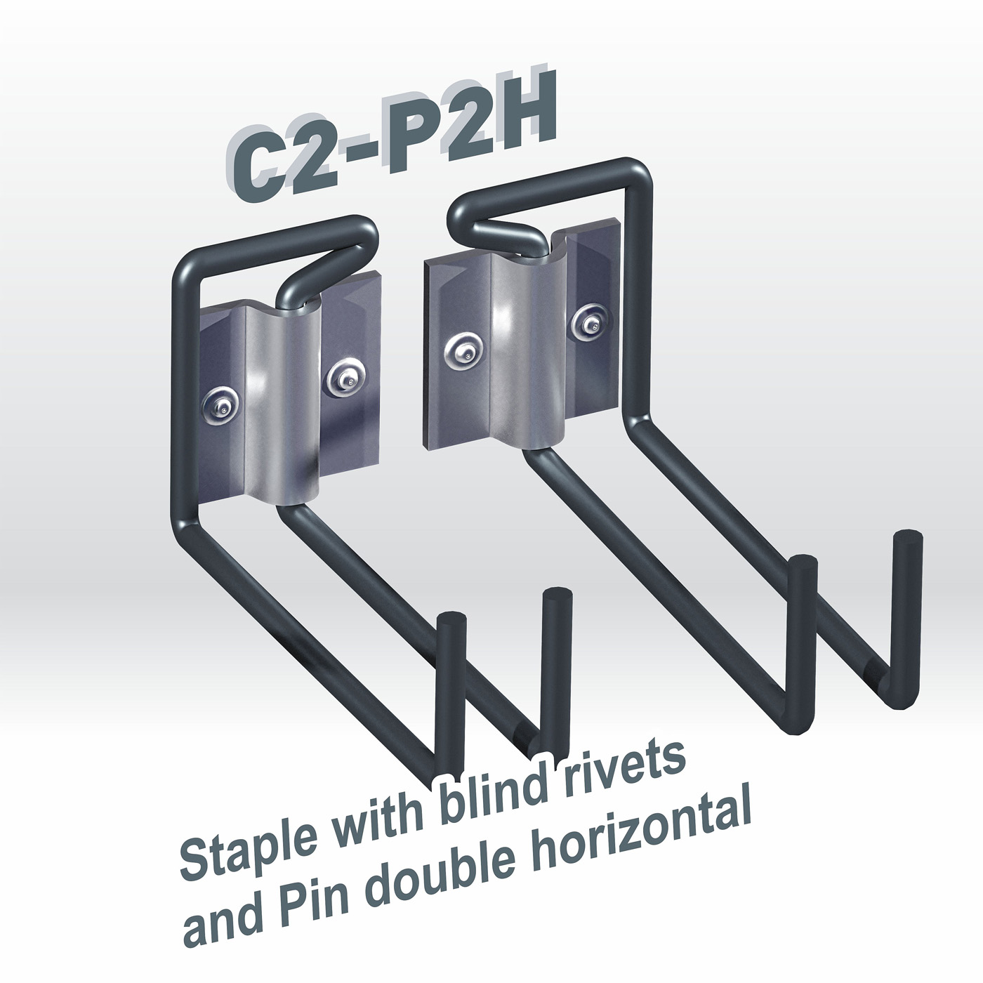
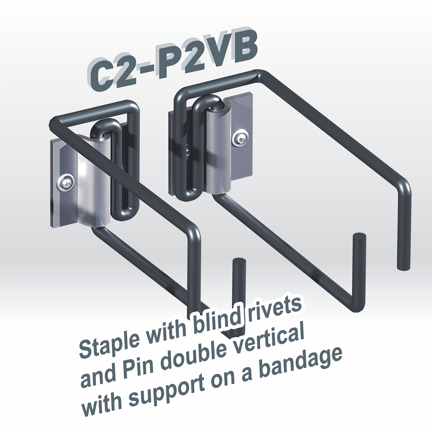
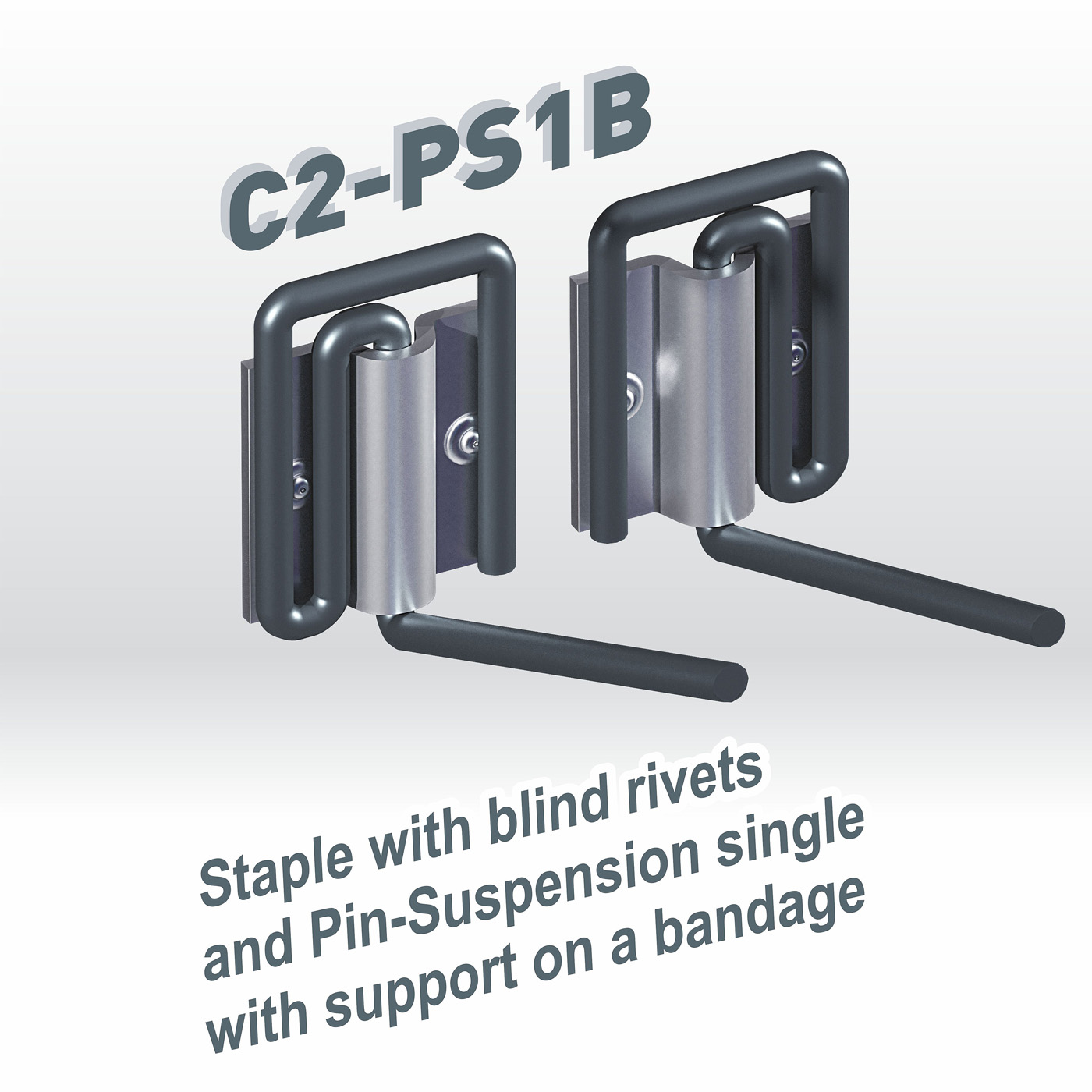
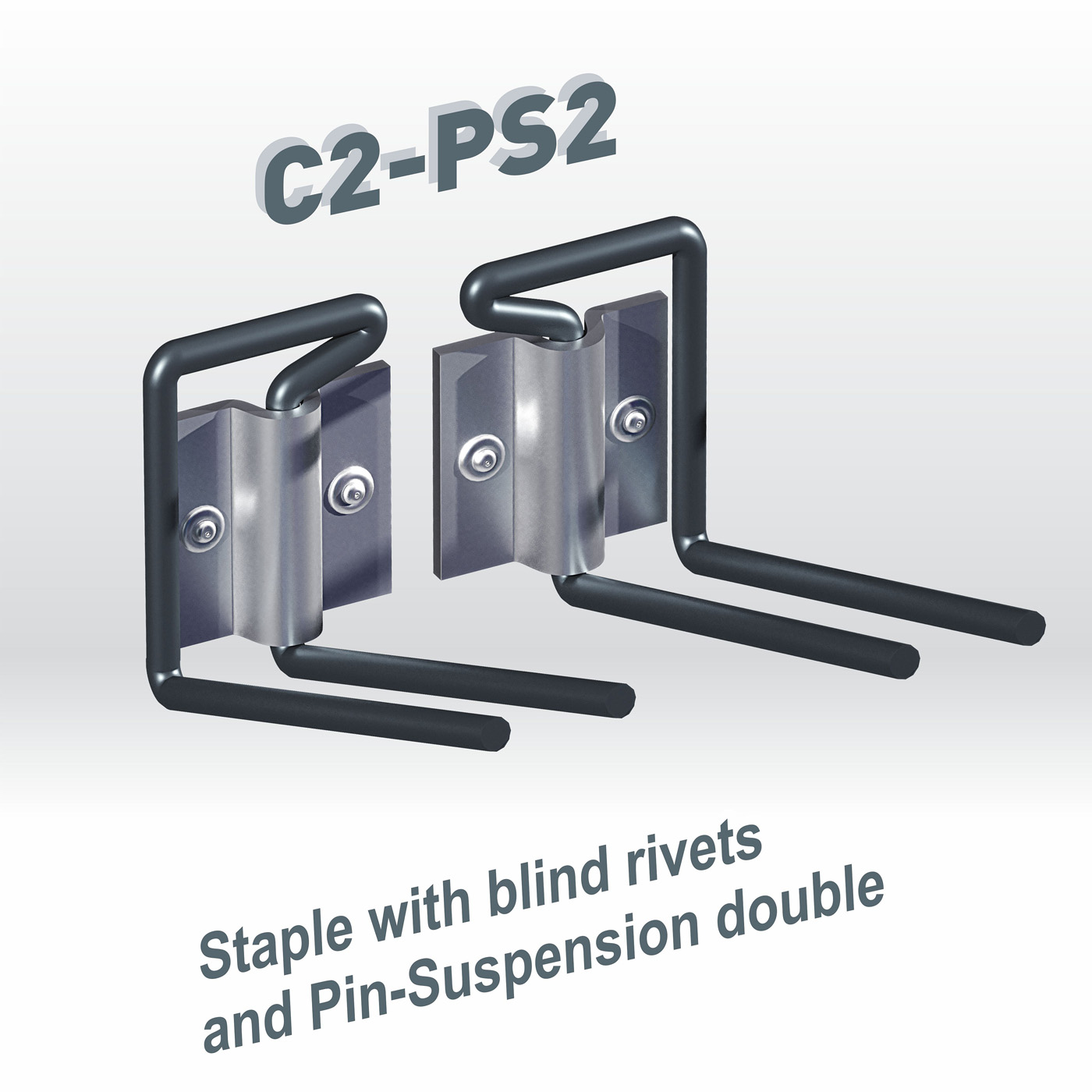
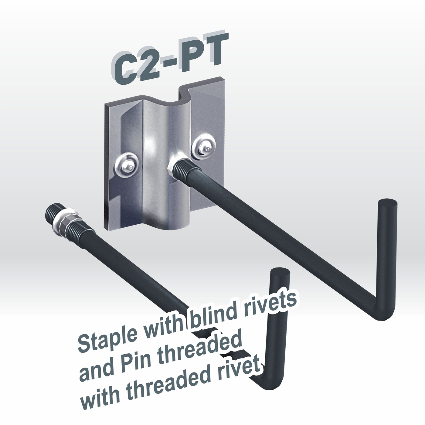
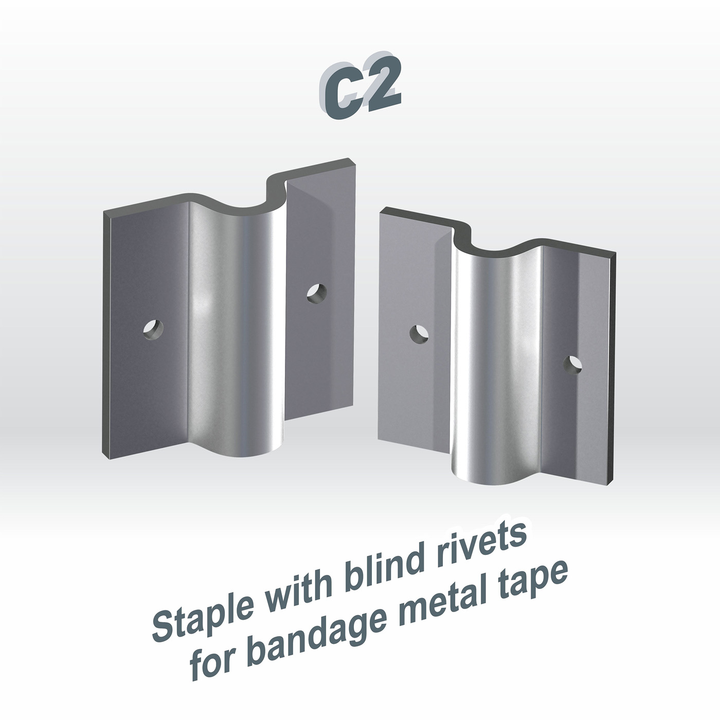
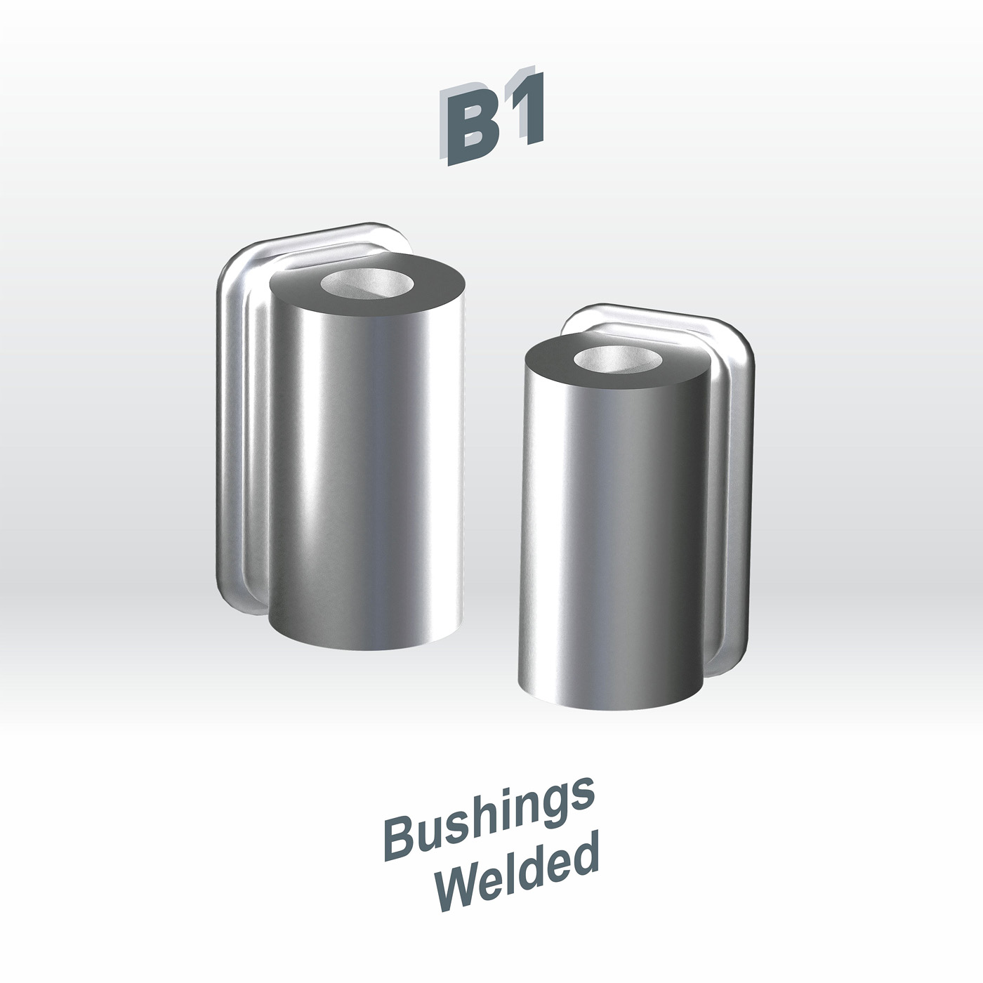
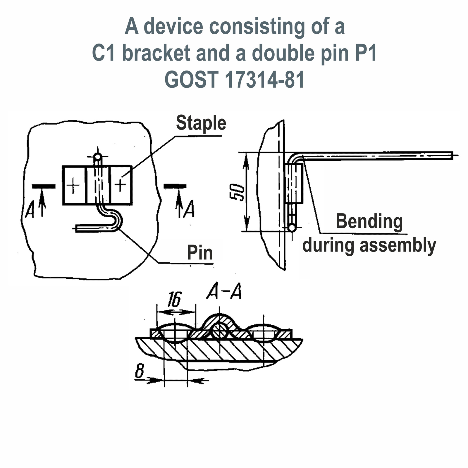
The methods of fixing the insulation depend on whether welding is allowed on the insulation surface. If welding is possible, the pins are welded to the insulated surface or installed in pre-welded brackets C1 or bushings V1, and if it is impossible to carry out welding work, the pins are attached to tie bands using special brackets C2 fixed to the bandage with the help of exhaust rivets, or, use threaded pins SHR screwed into threaded rivets placed on the bandage.

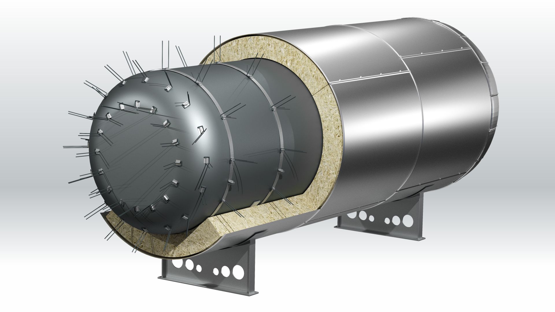
The thermal insulation material is impaled on the pins, after which the outer end of the pin must be bent at a distance of the insulation thickness. It is possible to use the attachment to the pin with a washer or a locking washer, which, when put on the pin, tightly press the thermal insulation layer to the insulated surface. When using a washer, the outer end of the pin is bent, and when using a locking washer, the excess part of it is cut off.
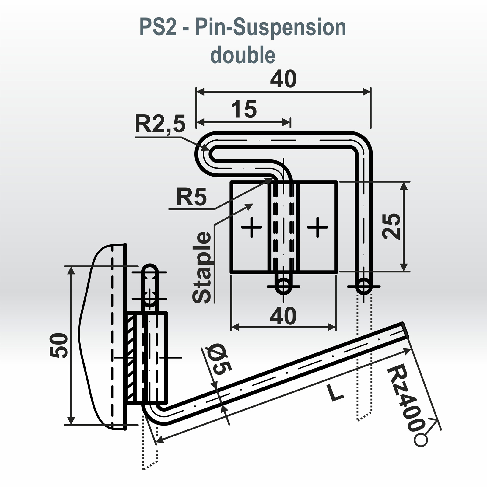
Removable parts, suspension pins (single PS1, double PS2 or threaded PS), are installed at the installation site of thermal insulation in the following ways:
● Welded directly to the wall of the device or pipeline;
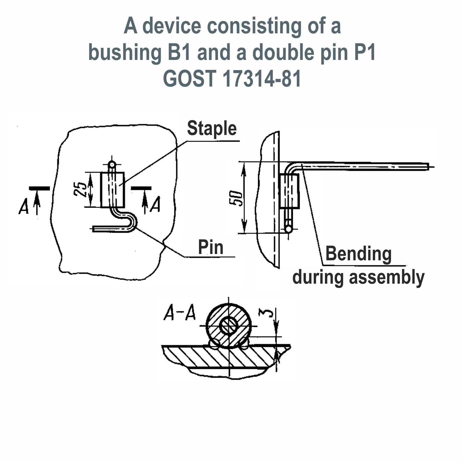
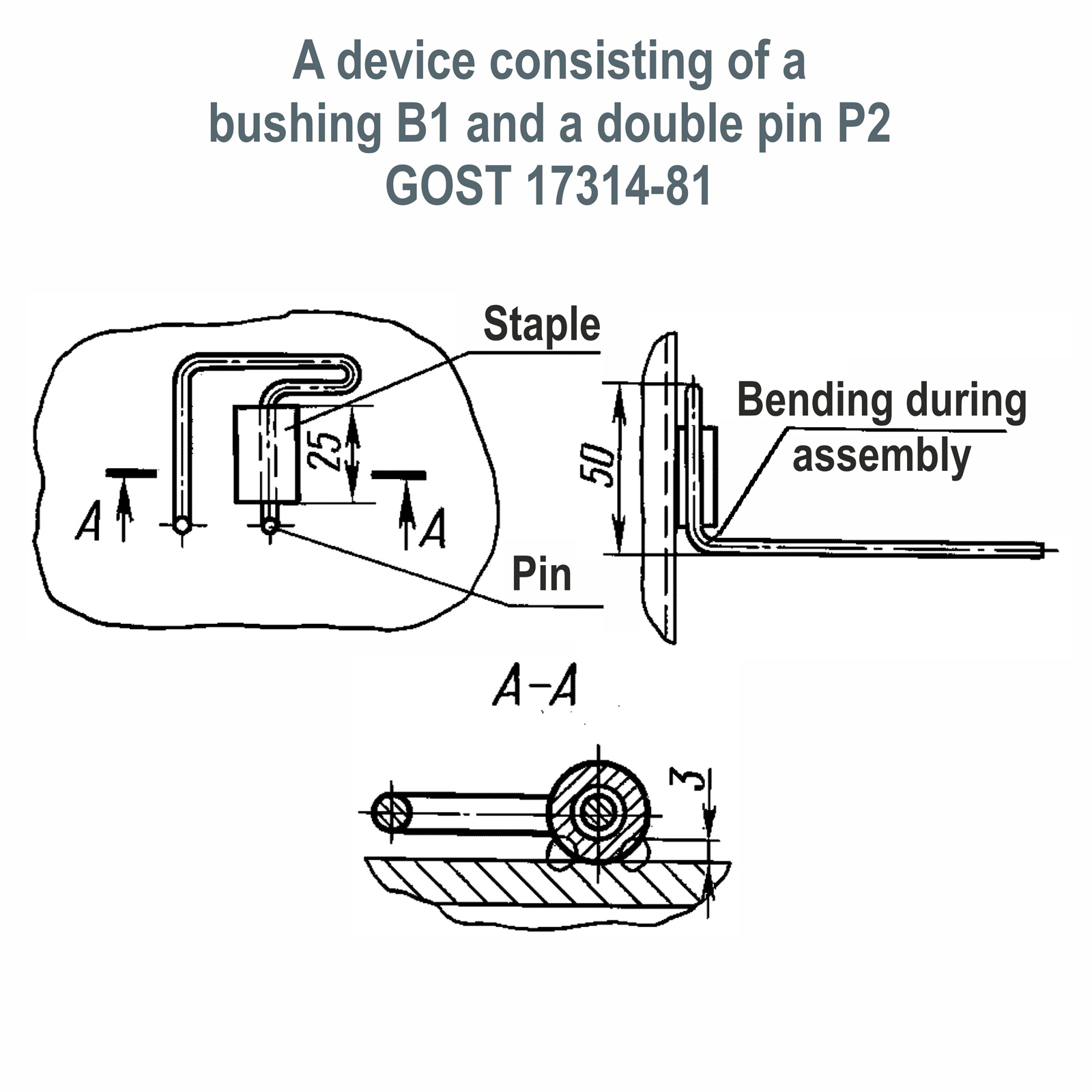
● Into bushings or staples previously welded to the wall of the device or pipeline;
● Into the brackets attached to the tie band with the help of exhaust rivets;
● Into the threaded rivets attached “on the tie band.
Types of pins used for fixing insulation, their placement on the surface depends on the thickness of the insulation.
* The dimensions of the pins are regulated according to GOST 17314-81.


EXAMPLES OF THE CONDITIONAL DESIGNATION OF PINS:
P1/60 GOST 17314-81-Single pin P1; insulation thickness up to 60mm
P1/100 GOST 17314-81-Single pin P1; insulation thickness up to 100mm
P2/50 GOST 17314-81-Double pin P2; insulation thickness up to 50mm
P2/100 GOST 17314-81-Double pin P2; insulation thickness up to 100mm
P2/160 GOST 17314-81-Double pin P2; insulation thickness up to 160mm
P2/200 GOST 17314-81-Double pin P2; insulation thickness up to 200mm
P2/250 GOST 17314-81-Double pin P2; insulation thickness up to 250mm
PS1/60 GOST 17314-81-Pin-suspension single PS1; insulation thickness up to 60mm
PS1/100 GOST 17314-81-Pin-suspension single PS1; insulation thickness up to 100mm
PS2/50 GOST 17314-81-Pin-suspension double PS2; insulation thickness up to 50mm
PS2/100 GOST 17314-81-Pin-suspension double PS2; insulation thickness up to 100mm
PS2/160 GOST 17314-81-Pin-suspension double PS2; insulation thickness up to 160mm
PS2/200 GOST 17314-81-Pin-suspension double PS2; insulation thickness up to 200mm
PS2/250 GOST 17314-81-Pin-suspension double PS2; insulation thickness up to 250mm
EXAMPLES OF CONDITIONAL DESIGNATION OF BRACKETS:
C1 GOST 17314-81-Welded bracket (attached to the device)
C2 GOST 17314-81-Rivet bracket (attached to a bandage)
B1 GOST 17314-81-Welded bushing (attached to the device)
EXAMPLES OF CONDITIONAL DESIGNATION OF DEVICES:
C1-P1/60 GOST 17314-81
(Welded bracket C1; single pin P1; insulation thickness up to 60mm)
C1-P2/160 GOST 17314-81
(Welded bracket C1; double pin P2; insulation thickness up to 160mm)
C2-P1/100 GOST 17314-81
(Bracket for bandage C2; single pin P1; insulation thickness up to 100mm)
C2-P1/160 GOST 17314-81
(Bracket for bandage C2; single pin P1; insulation thickness up to 160mm)
B1-PS1/160 GOST 17314-81
(Welded bushing B1; pin-suspension single PS1; insulation thickness up to 160mm)
B1-PS2/100 GOST 17314-81
(Welded bushing B1; pin-suspension double PS2; insulation thickness up to 100mm)
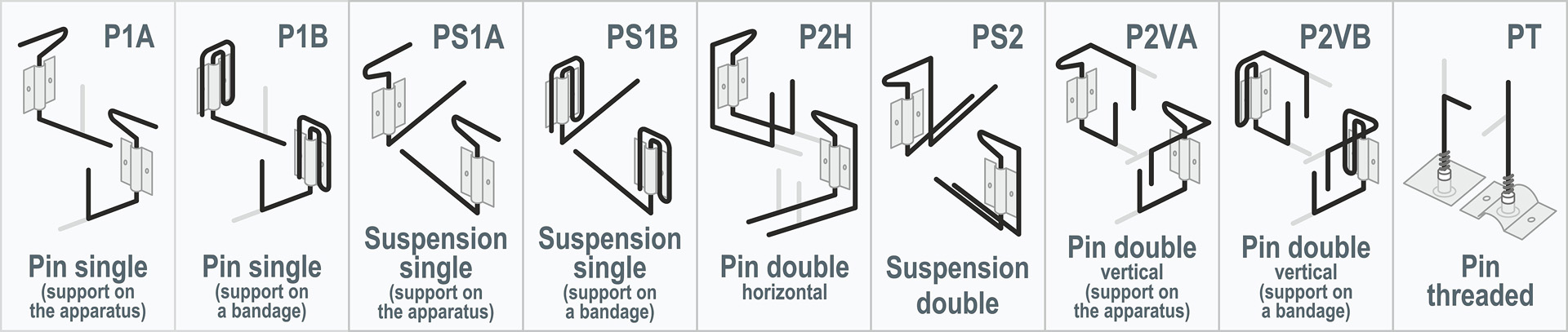
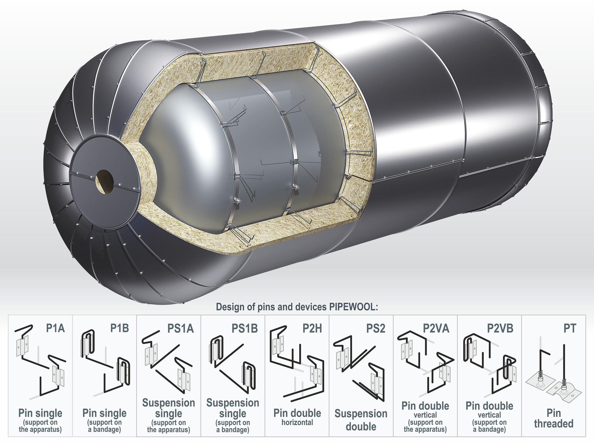
EXAMPLES OF THE CONDITIONAL DESIGNATION OF PINS:
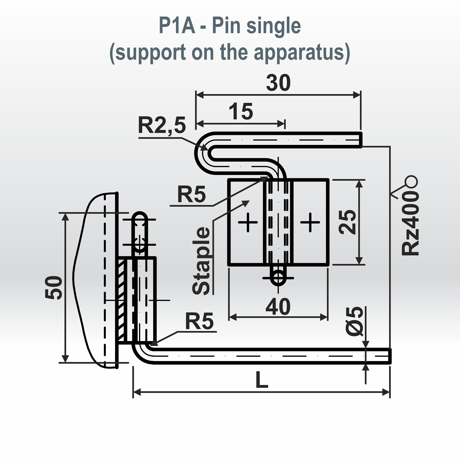
P1A/60 GOST 17314-81 (St. 5-O-H) – Single pin (support on the device); insulation thickness up to 60mm
P1B/100 GOST 17314-81 (St. 65G) – Single pin (support on the bandage); the thickness of the thermal insulation is up to 100mm
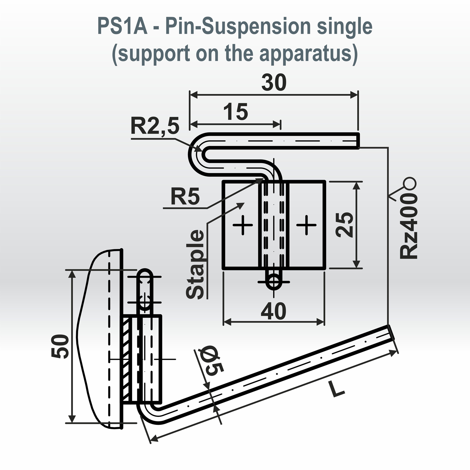
PS1A/60 GOST 17314-81 (St. AISI 304) – Single pin suspension (support on the device); insulation thickness up to 60mm
PS1B/100 GOST 17314-81 (St. 5-O-H) – Single pin-Suspension (support on the bandage); the thickness of the thermal insulation is up to 100 mm
P2G/200 GOST 17314-81 (St. 5-O-H) – Double horizontal pin; insulation thickness up to 200mm
PS2/160 GOST 17314-81 (St. 65G) – Double pin suspension; insulation thickness up to 160mm
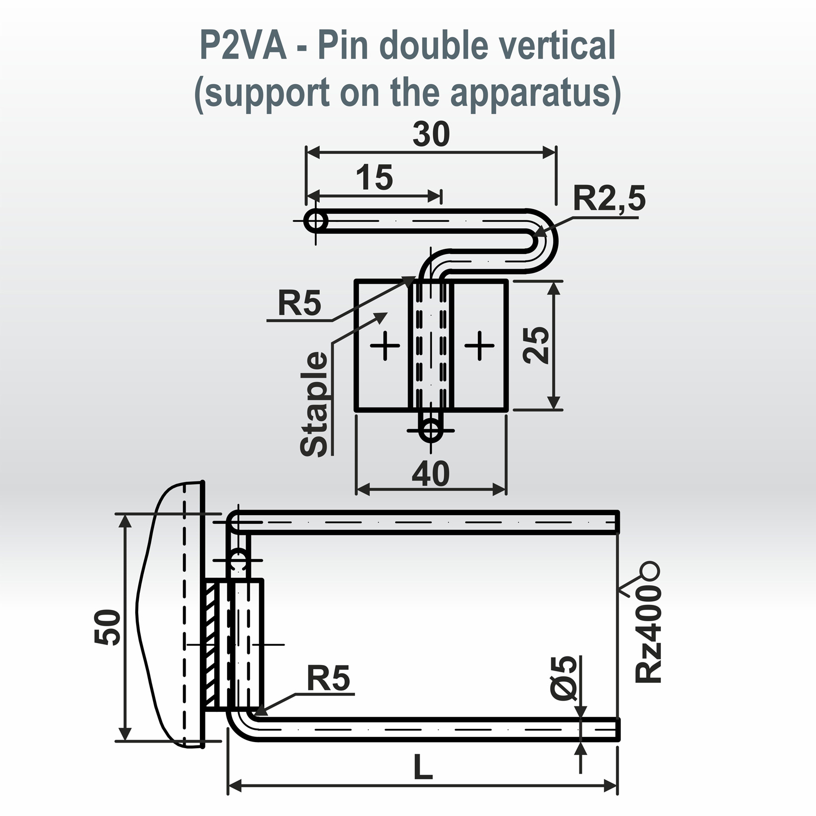
P2VA/100 GOST 17314-81 (St. 5-O-H) – Double vertical pin (support on the device); thermal insulation thickness up to 100 mm
P2VB/160 GOST 17314-81 (St. AISI 304) – Double vertical pin (support on the bandage); insulation thickness up to 160mm
PT/60 GOST 17314-81 (St. 5-O-H) – Threaded pin; insulation thickness up to 60mm
EXAMPLES OF CONDITIONAL DESIGNATION OF BRACKETS:
C1 GOST 17314-81 (St. AISI 304) – Welded bracket (attached to the device)
C1 GOST 17314-81 (St. 08PS) – Welded bracket (attached to the device)
C1 GOST 17314-81 (St. 08KP) – Welded bracket (attached to the device)
C1 GOST 17314-81 (St. AISI 403) – Welded bracket (attached to the device)
C2 GOST 17314-81 (St. 08PS) – A bracket on rivets (attached to a bandage)
C2 GOST 17314-81 (St. 08KP) – A bracket on rivets (attached to a bandage)
C2 GOST 17314-81 (St. AISI 301) – Bracket on rivets (attached to a bandage)
C2 GOST 17314-81 (St. AISI 403) – Bracket on rivets (attached to a bandage)
B1 GOST 17314-81 (St. 09G2S) – Welded bushing (attached to the device)
B1 GOST 17314-81 (St. 12X18H9) – Welded bushing (attached to the device)
EXAMPLES OF CONDITIONAL DESIGNATION OF DEVICES:
C1-P1A/60 GOST 17314-81 (St. AISI 304/St.AISI 304)
(Welded bracket C1; single pin P1; insulation thickness up to 60mm)
C1-P2G/160 GOST 17314-81 (St. AISI 304/St.AISI 403)
(Bracket welded C1; dual pin ø2 horizontal; insulation thickness up to 160 mm)
C2-P1B/100 GOST 17314-81 (St.08PS/St.5-OH-H)
(Clip for brace C2; single-pin P1; insulation thickness up to 100mm)
C2-P1B/160 GOST 17314-81 (St.08KP/St.65G)
(Clip for brace C2; single-pin P1; insulation thickness up to 160 mm)
B1-PS1A/160 GOST 17314-81 (St.09G2S/St.5-OH-H)
(Bushing welded B1; pin-suspension single PS1; insulation thickness up to 160mm)
B1-PS2A/100 GOST 17314-81 (St. 09G2S/St. 65G)
(Bushing welded B1; pin-suspension double PS2; insulation thickness up to 100mm)
TECHNICAL CHARACTERISTICS OF PINS FOR FIXING THERMAL INSULATION |
|---|
Pin designations | Pin Length (mm) | Product dimensions (mm) | Weight (kg) |
|---|---|---|---|
P1/60 (single); PS1/60 | 150 | 180 | 0,028 |
P1/100(single); PS1/100 | 190 | 220 | 0,034 |
P2/50 (double); PS2/50 | 150 | 331 | 0,051 |
P2/100(double); PS2/100 | 200 | 431 | 0,067 |
P2/160(double); PS2/160 | 260 | 551 | 0,085 |
P2/200(double); PS2/200 | 300 | 631 | 0,098 |
P2/250(double); PS2/250 | 360 | 751 | 0,120 |
The thickness of the thermal insulation layer: 60-250 mm. | |||
The length of the pins is used in such a way that its length exceeds the thickness of the thermal insulation by 50 mm.
The number of pins required for mounting depends on the installation step of the pins and the location of the insulation surface.
PIN INSTALLATION STEP (mm) |
|---|
Pin installation location | The step direction is Vertical | The step direction is Horizontal |
|---|---|---|
Vertical equipment | 500 | 250 |
Horizontal cylindrical equipment ▲ Upper half | 500 | 500 |
Horizontal cylindrical equipment ▼ Lower half | 250 | 500 |
Horizontal surfaces ▲ From above | 500 | 500 |
Horizontal surfaces ▼ From below | 250 | 500 |
The thermal insulation layers on the devices and tanks are fixed with pins, observing the following steps:
● On vertical sections, a step is set through 250 mm horizontally and 500 mm vertically.
● On horizontal lines in all directions through 500 mm, in the lower part along the circumference, the step is made equal to 250 mm, in the upper part along the circumference equal to 500 mm.
● On the bottoms of vertical and horizontal apparatuses and tanks with a diameter of more than 1 m, a step along the circumference through 250 mm, the diameter of the first circle is made 800 mm, each subsequent increases by 1000 mm.


